Team:CSIA SouthKorea
From 2012hs.igem.org
(→Project) |
(→Mechanism of the circuit) |
||
| Line 57: | Line 57: | ||
: Our construction of genetic circuit is based on "A synthetic oscillatory network of transcriptional regulators" by Michael B. Elowitz & Stanislas Leibler, and the article “A synchronized quorum of genetic clocks” by Danino et al. | : Our construction of genetic circuit is based on "A synthetic oscillatory network of transcriptional regulators" by Michael B. Elowitz & Stanislas Leibler, and the article “A synchronized quorum of genetic clocks” by Danino et al. | ||
| + | |||
| + | : [[File:system.jpg]] | ||
: In the diagram above, luxpL is a constitutive promoter and continuously expresses luxR. | : In the diagram above, luxpL is a constitutive promoter and continuously expresses luxR. | ||
| Line 65: | Line 67: | ||
: The parts we used in the assembly are as follows: BBa_R0062 for luxpR, BBa_R0063 for luxpL, BBa_C0060 for aiia, BBa_C0061 for luxI, and BBa_K082006 for luxR. We changed the part for luxR because we found that this part, although previously used by Wageningen_UR in 2011, is inconsistent and is not confirmed. | : The parts we used in the assembly are as follows: BBa_R0062 for luxpR, BBa_R0063 for luxpL, BBa_C0060 for aiia, BBa_C0061 for luxI, and BBa_K082006 for luxR. We changed the part for luxR because we found that this part, although previously used by Wageningen_UR in 2011, is inconsistent and is not confirmed. | ||
| - | |||
==Design of the circuit== | ==Design of the circuit== | ||
Revision as of 11:34, 16 June 2012
Our team is consisted of four students who are fond of thinking creatively, sharing our knowledge with others and making contributions to the society. We hope that iGEM 2012 could be a great opportunity for us to get our feet wet in the field of synthetic biology and interact with many other students around the world who are also interested in this field! Since our school does not have facilities for wet lab, team CSIA_SouthKorea asked professor In-Geol Choi in Korea University for guide. Professor Choi, Instructor Hyeok-Jin Ko and Hongjae Park let us to be familiar with synthetic biology, taught us how to use basic lab facilities and helped every part in our projects :)
Contents |
Team
- Our team and school is introduced in this page!
Project
Abstract
- Based on the design of V.fischeri, we placed luxR gene under luxpL promotor and placed luxI, Aiia, and GFP gene under luxpR promotor. In this V.fischeri quorum sensing system1, LuxI synthase produces an acyl-homoserine lactone (AHL), which is a small molecule diffuses extracellularly and triggers quorum sensing. When AHL binds to LuxR, it produces LuxR–AHL complex that activates luxI promoter. This also activate GFP genes, so fluorescence can be detected. AiiA 'represses'2 continuing activation of luxI promotor by degrading of AHL. Therefore, fluorescence may have the cycle under right conditions.
- This network which an activator triggers its own repressor illustrates a concept of synthetic oscillator design. Further, theoretical work shows how an autoinducer leads synchronized oscillations in a single cell and a population of cells3.
- The team got interested in synchronized oscillator while reading Team Wageningen's 2011 project. However, we modified their model a little to increase the probability of success in experiment by using each luxpL and luxpR promoter for only one time.
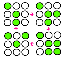
- Our research goal is to build the circuit for synchronized oscillator and use them for display. Based on the idea that oscillatory period differs for different cell population, we plan to have a 3 x 3 array, each well consisted of different colonies. The difference in period of GFP expression will allow to display certain figure at certain time.
- In the world where people suffer from energy deficiency, we expect that this technology could be applied to many different areas. Among them, we think the most successful adaptation would be as an alternative for signs, secret messages and night stand.
Introduction of E.Coli display using repressilator
- Our introduction further explains the system and goals.
Mechanism of the circuit
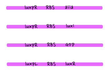
- Our construction of genetic circuit is based on "A synthetic oscillatory network of transcriptional regulators" by Michael B. Elowitz & Stanislas Leibler, and the article “A synchronized quorum of genetic clocks” by Danino et al.
- In the diagram above, luxpL is a constitutive promoter and continuously expresses luxR.
- luxpR is an inducible promotor that is activated by luxR-AHL complex. AHL is the auto-inducer molecule N-(3-oxohexanoyl)-homoserine lactone that can diffuse across other cell membranes, gives many cells identical AHL levels, and creates quorum sensing by synchronizing AHL dependent gene expression. Under luxpR, there are both luxI, which produces AHL, and aiia, which degrades AHL, which generates feedback loops that controls the amount of luxR-AHL complex. (LuxI only increases level of AHL, which makes positive feedback loop, and aiia degenerates AHL, which builds negative feedback loop)
- Green Fluorescent protein is also under luxpR and demonstrates AHL concentration through its brightness at certain time point. Because rate of synthesis in luxI and rate of degradation in aiia differs, there exists a certain condition that enables periodic oscillation in AHL concentration.
- The parts we used in the assembly are as follows: BBa_R0062 for luxpR, BBa_R0063 for luxpL, BBa_C0060 for aiia, BBa_C0061 for luxI, and BBa_K082006 for luxR. We changed the part for luxR because we found that this part, although previously used by Wageningen_UR in 2011, is inconsistent and is not confirmed.
Design of the circuit
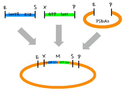
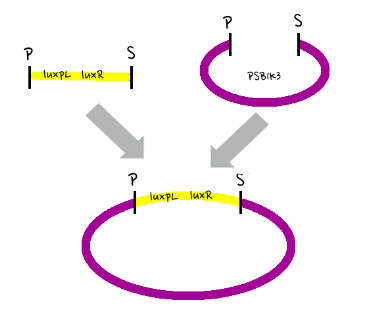
- Since gene parts were already on the partsregistry, we linked them using Gibson assembly. However, our model is different from original plasmids used by Danino et al. We used luxpR only once to bring aiia, GFP, and luxI protein under the promoter. And we used luxpL promoter only once, placing luxR under it.
- Since RBS sequence was short, we used gibson assembly to synthesize those four parts.
- Then, by connecting those four parts and restriction enzymes, we made luxpR-aiia part to be cutted by EcoRI and SpeI, luxpL-luxR part by PstI and SpeI, and GFP-luxI by XbaI and PstI(illustrate below!).
- Then, by using iGEM standard protocol, in two different types of vectors, PSB1A2 and PSB1K3, we ligated the parts with vectors as shown below.
Variables that determine period of the circuit
- According to the thesis 'A synthetic oscillatory network of transcriptional regulators' by Michael B. Elowitz & Stanislas Leibler, he period of oscillations in such networks is determined mainly by the stability of the protein that is expressed by the synchronized oscillators.
- Further, 'A synchronized quorum of genetic clocks' by Danino et al. suggests that effective AHL dissipation rate affects the period of the oscillations. In other words, this means that flow rate significantly affects period. According to their experiment, at high flow rate, the stabilized oscillations exhibit period of 90+-6 min and mean amplitude of 54+-6 GFP arbitrary units. At low flow rate, they observed a period of 55 +-6min and amplitude of 30 +-9GFP arbitrary units. Overall, when they changed the flow rate from 180 to 296 micrometer per minute, the team observed an increasing oscillatory period from 52 to 90 min.
- Both factors are beyond our control as we do not have proper equipments to control both factors.
Simulation of the display
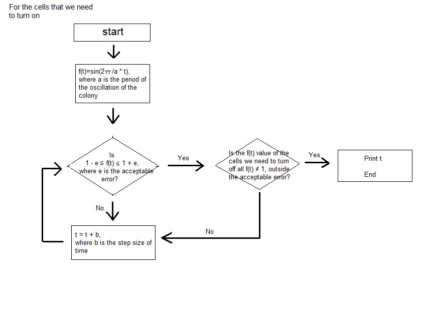
- Before doing the wet lab, in order to predict the results of our experiment, we did computer simulation of the light bulbs of the night stand that we are trying to make with colonies of Escherichia coli.
- We simplified the oscillations of GFP expression in each E. coli colonies into sine function on time. Therefore, when the periods of the oscillation of the E. coli colonies are entered as input, in each cell of the 3*3 array, which represents the 9-well-plate, the sine function with each of the entered period is corresponded. We set -1 as the value of the sine function when the GFP expression is the lowest and 1 as the value of the sine function when the GFP expression is the highest. We assumed that the GFP expression of all the colonies started from the sine function value of 0.
- Then, when the step size of time, tolerance of error, the picture that we are trying to express with the night stand are entered as the input, the program calculates the sine function value of each cell at certain time and seeks for the point where only the colonies of certain cells have the sine function value close to 1 inside the tolerance of error that was entered as input. Until the point is reached, the program keeps on calculating the sine function value of each colony by increasing the elapsed time by the step size of time that was entered as input.
- The program continuously shows the process; we can actually see the numerical value of sine function of each cell at each moment. The program stops running at the time when the picture that we want to obtain (when the certain cells that make the picture have sine function values very close to 1) is expressed, and the program prints the elapsed time as output.
- As a result, we are able to calculate the time needed to express the picture that we want to obtain using the light bulbs (colonies of E. coli in each cell) of the night stand (9-well-plate).
- This is the instruction of how the values are put into the program.
Protocols
- Our protocol is based on 3A assembly protocol provided by iGEM. Standard assembly is divided into 'growing', 'miniprep', 'restriction digest', 'ligation' and 'transformation'. The following texts are from partsregistry.
Restriction Digest
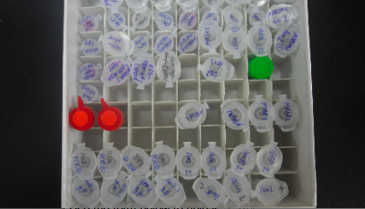
- 1. Clean the lab bench by wiping down with 70% ethanol and paper towels. Keep all enzymes and buffers used in this section on ice.
- 2. Label four 0.6 tubes: Part A, Part B, pSB1C3 (linearized plasmid backbone), and RFP Control
-
- 3. Add 500ng of DNA to the appropriate tube.
- 4. Pipet 5ul of Buffer 2 to each tube.
- 5. Pipet 0.5ul of BSA to each tube.
- 6. In the Part A tube: Add 1ul of EcoRI enzyme, and 1ul of SpeI enzyme.
- In the Part B tube: Add 1ul of XbaI enzyme, and 1ul of PstI enzyme.
- In the pSB1C3 tube: Add 1ul of EcoRI enzyme, and 1ul of PstI enzyme.
-
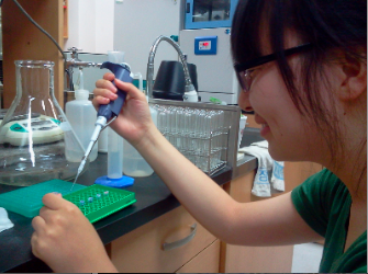
- 7. In the RFP Control tube: Add 1ul of EcoRI enzyme, and 1ul of PstI enzyme.
- 8. The total volume in each tube should be approximately 50ul. Mix well by pipetting slowly up and down 5x. Be gentle, and do not vortex. Spin the samples for 5 seconds in a microcentrifuge, or flick them to collect all of the mixture to the bottom of the tube.
- 9. Incubate the restriction digests at 37°C for 30 minutes, then 80°C for 20 minutes. We use a thermocycler, but a waterbath and an accurate thermometer works well also!
The digested DNA can be stored at 4°C for a few days. For longer storage, keep at -20°C.
Ligation
- 1. Clean the lab bench by wiping down with 70% ethanol and paper towels.
- 2. Thaw T4 DNA Ligase Reaction Buffer at room temperature. Keep the T4 DNA Ligase in the freezer until you're ready to use it.
- 3. Add 11μl of H2O to a 200μl PCR tube.
- 4. Add 2ul from each of the digest to the tube, Add 2μl of 10XT4 DNALigase Reaction buffer to the tube
- 5. Add 1ul of T4 DNA Ligase.
- 6. Mix by gently pipetting up and down 3x. Do not vortex; this inactivates the enzymes. Place tube in microcentrifuge for a quick 5 second spin or flick the tube to collect the mixture at the bottom. The total volume in each tube should now be 20 μl. Ensure the ligation is well-mixed by flick- ing the tube. You can spin the tube in a micro-
centrifuge for a few seconds to collect the liquid in the bottom of the tube again.
- 7. Incubate the reaction mix at room temperature for 10 min.
- 8. Incubate the reaction mix at 80C for 20 min. The 80C incubation deactivates the enzyme and improves transformation efficiency.
- 9. Store the ligation mix at -20C or proceed immediately to the transformation step.
Transformation
- 1. Clean the lab bench by wiping down with 70% ethanol and paper towels.
- 2. Keep all materials on ice unless otherwise specified! This will help make the cells more competent and easier to transform.
- 3. Keeping the tubes on ice for 10 minutes, pipet up and down gently 5x to re-suspend the cells.
- 4. Add 5ul of RFP control DNA (20ng/ul) into one the Transformation Control tube. Add 2ul of the ligated New Part product to its appropriate tube, and do the same for the Ligation Control. When adding the DNA pipet gently up and down 5x to mix the contents.
-
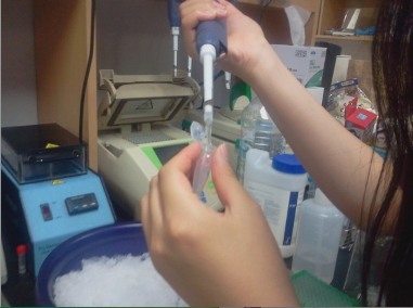
- 5. Incubate the DNA and cell mixtures on ice for 5 minutes.
-
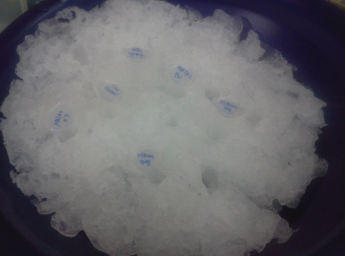
- During the incubation, pre-heat the waterbath to 42° Celsius.
- 6. Place the tubes into the waterbath for 90 seconds. Place the tubes back on ice for 1 minute.
- 7. Add 200ul of SOC media to each tube. Pipet up and down gently to mix.
- 8. Label three agar plates containing the appropriate antibiotic with a corresponding tube.
- 9. Pipet 200ul of the Transformation Control onto the appropriately labelled plate. Carefully pour 3-6 glass beads into the plate. Spread evenly over the surface of the agar by gently shaking back and forth. Repeat this step for the other tubes.
- 10. Place the agar plates into the incubator with the agar side facing up, lid facing down. Incubate the agar plates at 37° Celsius for 12-14 hours. Alternately, incubate at room temperature for 24 hours.
-
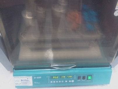
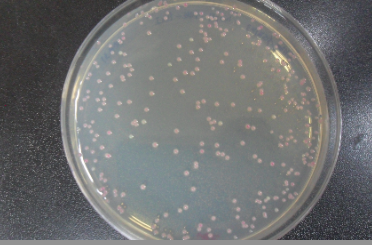
- 11. Check for red colonies the next day! Plates can be stored at 4° Celsius for a few days.
-
Applications
- 1. Electronic display
- While working on the project, we wondered if we could synchronize the period of each cell in the well plate and let them have the same period of oscillation. If this is possible, then we would be able to let the bacteria glow and turn off the light in the same period, and therefore use it to make certain signals that we want on the well plate. It can be some shapes such as square, circle, cross, or star; it can be some letters such as a, b, or c; and if the technique can be applied to larger plate, then we would even be able to display a phrase or a short sentence on the plate. This might as well work as electronic displays that are widely used nowadays for advertising the stores.
- If the glowing bacteria-project that we are working on can be produced with enough light intensity and possible to program the cells of the plate, then it will be truly beneficial both for people and the environment. Currently the electricity deficiency is a huge problem all over the world. Great dark-outs occur because of excessive usage of electricity, and people are paying a great amount of money for using the electricity. If we can replace these electronic displays with glowing bacteria-display, then we will be able to save quite amount of electricity usage and thus contribute to the saving of electricity.
- 2. Light source
- Second possible application is the usage of glowing bacteria as the light sources, such as reading lamps or small-sized flashlights. It is true that certain level of light intensity is necessary in order to be used in the way proposed. However, we do believe that after some extensive research and laboratory, enough level of light intensity will be reached.
- If the light source using biological method (glowing bacteria) is developed, it will have positive impact on the society. First, since it glows with no need of external power source, battery and electricity will be saved for other usages. Second, the biological-light source will be able to be used by people in the regions where electricity supply isn’t enough or easy. Even now, there are regions where people can’t easily get access to electricity, and thus have to live in dark when the sun sets. If our project can be developed and applied to making a self-glowing light source, then it will surely bring some benefits.
Outreach & contribution
- Outreach will lead you to a page about our introducing brochure about synthetic biology, and Synbio class in Suri Nature School.
Brainstorming
- Please see our Brainstorming section. We have more than ten ideas explained!
Notebook
- Please see our Notebook. We have an extensive log from September 2011 on our experiments! :)
Safety
- In this page, Safety , you will see our team CSIA_SouthKorea's lab safety practice and learnings.
References
- Danino et al, A synchronized quorum of genetic clocks”, Nature vol. 463, 326-330 (2010)
- Liu, D. et al. Mechanism of the quorum-quenching lactonase (AiiA) from Bacillus thuringiensis. 1. Product-bound structures. Biochemistry 47, 7706–7714 (2008).
- Garcia-Ojalvo, J., Elowitz, M. & Strogatz, S. Modeling a synthetic multicellular clock: repressilators coupled by quorum sensing. Proc. Natl Acad. Sci. USA 101, 10955–10960 (2004).
- http://avena.pw.usda.gov
<forum_subtle />
 "
"
